Nominal duct, casing and structural hole are not the same thing
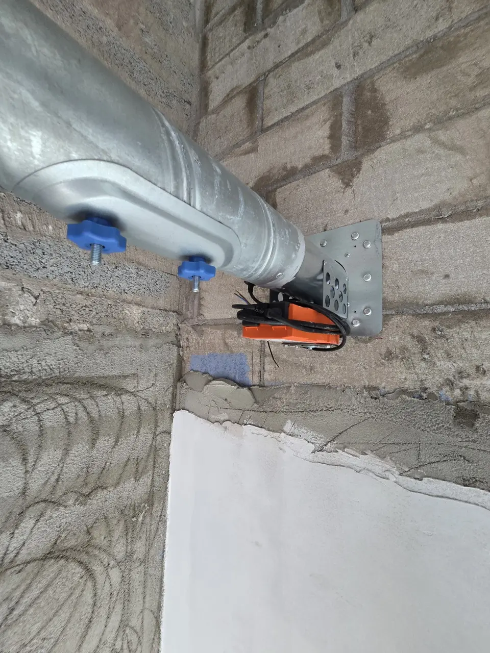
A fire damper opening can be wrong even when its overall size looks right. The datum also matters: the casing may project below the nominal duct, and the tested method can then require clearance and aperture lining outside that casing.
The five-stage dimension chain
- Nominal duct or spigot: the scheduled airway connection size.
- Damper casing or installation frame: the real body that passes through or sits at the penetration.
- Finished aperture: casing or frame plus the tested clearances required by the selected method.
- Aperture lining: board fitted around the internal reveal where the method requires it.
- Structural hole to form: the cut made before the reveal lining and tested sealing arrangement are installed.
Why the bottom datum causes mistakes
If the known drawing level is the bottom of the nominal duct, the structural cut may have to start below it. The required drop can include:
“10 mm below the casing” does not mean “10 mm below the duct”. Treating those as the same datum moves the entire opening upward and can leave insufficient room below the damper body.
Worked example: circular spigot through a rectangular casing
This example follows the published BSB FD Series Type C / Angle Frame geometry used by the VentTools FD-C-AF path. It is an explanation of the chain, not a universal rule for circular dampers.
| Stage | Width / height | Reason |
|---|---|---|
| Nominal duct | Ø250 mm | Selected scheduled connection |
| Actual spigot O.D. | Ø247 mm | Published D − 3 mm connection |
| Rectangular casing | 309 × 309 mm | 247 mm spigot plus 31 mm casing projection each side |
| Nominal finished aperture | 329 × 329 mm | 10 mm clear at each opposite casing edge |
| Structural cut with 12.5 mm lining | 354 × 354 mm | One 12.5 mm reveal board at each opposite edge |
For the bottom setting-out line in this example, the cut begins 52 mm below the nominal duct edge: 29.5 mm casing projection + 10 mm clearance + 12.5 mm lining.
Checks before issuing a builder's hole
- Read the physical label and match the manufacturer, product and variant.
- Select the tested method that matches the actual wall, floor or supporting construction.
- Confirm whether dimensions are nominal duct, outside casing or outside installation frame.
- Check whether the actuator, shroud, flange or installation plate changes the controlling width.
- Confirm whether the published opening is finished, structural, minimum, maximum or a permitted range.
- Identify lining as reveal lining, face pattress, penetration batt or infill—these are not interchangeable.
- Check required separation from adjacent construction and other dampers.
- Keep access, duct supports and breakaway connection requirements with the opening information.
Controlling information
The current manufacturer installation manual, Declaration of Performance, approved fire strategy and project-specific detail remain controlling. VentTools disables or marks a method for review where the necessary geometry cannot be established.
Worked-example source: BSB FD Series dimensions and installation methods.
Calculate a verified opening